Frequently Asked Questions
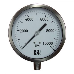
Pressure Gauges
| Various Pressure Units | kPa |
|---|---|
| 1 bar | 100 |
| 1 mbar | 0.100 |
| 1 PSI | 6.89476 |
| 1 cm of Mercury | 1.330 |
| 1 inch of mercury | 3.386 |
| 1 kg/cm2 | 98.067 |
| 1 metre of water | 9.789 |
| 1 foot of water | 2.984 |
| 1 inch of water | 0.249 |
| 1 atmosphere | 101.325 |
The gauge may have been dropped or over pressured.
Pressure build up in the cast – to fix relieve pressure by removing and reinserting the rubber bung at the top of the gauge.
To avoid early fatigue from vibration or to dampen the indication due to pulsating pressure.
Gauges should not be exposed to excessive heat or cold, as this may cause them to indicate incorrectly. Working fluids at a temperature above 60°C should not be allowed to enter the gauge. Remember – if a gauge shank cannot be grasped by hand without discomfort, it is working at too high a temperature. (AS1349-1986).
Compressor Components
Unloader leaks are usually caused by a faulty check valve.
The flow capacity charts for all of our ASME safety valves are shown under the Products section of our web page.
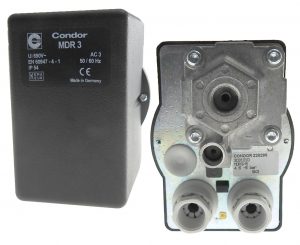
Cut-out pressures are adjustable from 60 PSI to 250 PSI with the standard silver spring. The differential (difference between cut-out and cut-in pressures) is typically set at the factory at roughly 15% of the cut-out pressure. This is usually a suitable differential and will not normally need to be re-adjusted.
We offer a wide range of pilot valves and unloading valves for many applications:
Pilot Valve
The P25 valve is an adjustable pilot valve with a ¼” NPT inlet and an ⅛” NPT outlet port which can be used to pilot head unloaders or used with a throttle control to slow down the engine during cut-out. The P25 pilot valve has a 3/8-16 UNC mounting boss, and comes standard with an unloading sleeve for gas engine warm up. Options include a toggle for one hand unloading, a lock out thumbscrew for dual systems control, and a ¼” nipple for the inlet. Refer to the Pilot Valve section of our Products web page for details on the cut-in and cut-out ranges.
Venting Pilot Valve
The P25V unloader incorporates all of the P25 options along with a vent valve to unload the compressor discharge after cut-out. The vent valve on the P25 has a ¼” compression fitting which must be connected to the compressor discharge line. The P25V offers all of the same options as the P25, except for the mounting boss.
Venting Unloader with Check Valve
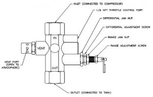
We offer a complete line of self-contained Continuous Run Vent unloaders. These valves incorporate an adjustable pilot valve, vent unloader, and check valve that perform all of the functions required for continuous run compressors. Options include a ¨û” NPT tapped port for throttle control as a gas engine, a toggle unloading lever for one-hand warm up, and a vent port muffler. Depending on flow and space requirements, we offer the Mark II, Mark III and Mark IV series of valves. Visit the Products section of our web site to find out which valve is right for you.
We offer two standard types of pressure relief devices for air:
- A safety relief valve, or pop-off valve, is set to pre-determined pressure using a spring force to counteract the air pressure force. When the force created from the air pressure becomes greater than the spring force, the valve ‘pops’ fully open and vents air to the atmosphere. Safety relief valves are sized in such a manner that the valve will always have a greater flow capacity than the source creating the air pressure (i.e. an air compressor). The valve will remain open until a reseat pressure is reached. This reseat pressure varies with valve type and is usually between 35% to 75% of the set pressure. Control Devices have eight series of valves that are manufactured in accordance with Section VIII of the ASME Boiler and Pressure Vessel Code. Control Devices also manufacture a wide range of non-code valves. See our Products section for information on the valve types.
A relief valve is set to a pre-determined pressure with a spring force counteracting the force created by the pressure from the air. When the force created from the pressure of the air becomes greater than the force of the spring, the valve will start to open and flow to atmosphere. As the pressure continues to increase, the valve will open further, allowing more flow. As the pressure decreases, the valve will close near the pressure at which it opened.
We offer a wide range of pilot valves and unloading valves for many applications:
Pilot Valve
The P25 valve is an adjustable pilot valve with a ¼” NPT inlet and “1/8” NPT outlet port which can be used to pilot head unloaders or used with a throttle control to slow down the engine during cut-out. The P25 pilot valve has a 3/8-16 UNC mounting boss, and comes standard with an unloading sleeve for gas engine warm up. Options include a toggle for one hand unloading, a lock out thumbscrew for dual systems control, and a ¼” nipple for the inlet. Refer to the Pilot Valve section of our Products web page for details on the cut-in and cut-out ranges.
Venting Pilot Valve
The P25V unloader incorporates all of the P25 options along with a vent valve to unload the compressor discharge after cut-out. The vent valve on the P25 has a ¼” compression fitting which must be connected to the compressor discharge line. The P25V offers all of the same options as the P25, except for the mounting boss.
Venting Unloader with Check Valve
We offer a complete line of self-contained Continuous Run Vent unloaders. These valves incorporate an adjustable pilot valve, vent unloader, and check valve that perform all of the functions required for continuous run compressors. Options include a ¨û” NPT tapped port for throttle control as a gas engine, a toggle unloading lever for one-hand warm up, and a vent port muffler. Depending on flow and space requirements, we offer the Mark II, Mark III and Mark IV series of valves. Visit the Products section of our web site to find out which valve is right for you.
We offer two standard types of pressure relief devices for air:
- A safety relief valve, or pop-off valve, is set to pre-determined pressure using a spring force to counteract the air pressure force. When the force created from the air pressure becomes greater than the spring force, the valve ‘pops’ fully open and vents air to the atmosphere. Safety relief valves are sized in such a manner that the valve will always have a greater flow capacity than the source creating the air pressure (i.e. an air compressor). The valve will remain open until a reseat pressure is reached. This reseat pressure varies with valve type and is usually between 35% to 75% of the set pressure. Control Devices have eight series of valves that are manufactured in accordance with Section VIII of the ASME Boiler and Pressure Vessel Code. Control Devices also manufacture a wide range of non-code valves. See our Products section for information on the valve types.
- A relief valve is set to a pre-determined pressure with a spring force counteracting the force created by the pressure from the air. When the force created from the pressure of the air becomes greater than the force of the spring, the valve will start to open and flow to atmosphere. As the pressure continues to increase, the valve will open further, allowing more flow. As the pressure decreases, the valve will close near the pressure at which it opened.
- Loosen only range screw jam nut.
- Turn range screw clockwise to raise cut-out and cut-in pressure levels and counter clockwise to decrease cut-out and cut-in levels.
- Start compressor and note cut-out and cut-in pressures. Make adjustments as necessary using range screw and, when acceptable, tighten range screw jam nut. Proceed as follows, only if it is necessary to make a differential adjustment.
- Adjust the cut-in pressure to the desired level per Steps 1 through 3 as above.
- Loosen differential screw jam nut and turn differential screw clockwise to raise cut-out pressure and counter clockwise to decrease the cut-out pressure. Tighten differential screw jam nut when the desired cut-out pressure is set. Since Step 5 should not change the desired cut-in pressure set in Step 4, the adjustment is now complete.
FOOD & CATERING
After all, you would not cross a busy road without taking adequate precautions for your safety. A busy road is a hazard; a hazard is the potential to cause harm, therefore we should take the necessary measures to minimise (control) the risk of being run over. Controlling a risk will not always eliminate it, but it will reduce the chances of someone getting hurt. If you substitute roads for food you have a similar scenario.
HACCP was originally developed by NASA in the US, for astronauts. The thought of someone suffering food poisoning symptoms, while travelling in space in weightless conditions confined with others in a small capsule does not bear thinking about. It was therefore decided that random quality control testing at the end of production was not a sufficiently safe system.
HACCP is a system that was devised to provide quality assurance throughout the process of food manufacture by establishing critical monitoring (control) points. This system aims to ensure the safety of the food from farm to plate. Although HACCP in its full form is mainly used in the manufacturing industry, a slightly ‘watered down’ version called Hazard Analysis, has been set out in the Food Safety (General Food Hygiene) Regulations 1995 and is now a legal requirement for all food businesses. New regulations will come into force on 1st January 2006 internationally and will require all food businesses to implement a documented HACCP system or a system based on HACCP principles after this date.
The seven principles of HACCP:
- Conduct a Hazard Analysis – identify the food safety hazards associated with your business, e.g. multiplication of harmful bacteria.
- Determine the Critical Control Points – if there is no later stage in the process that will then make the food safe, e.g. cooking, then it is a CCP. An easy way to do this is to ask the question “What if?”
- Establish Critical Limits – temperature limits, below or above which food will not be acceptable.
- Monitor and Control the CCPs – if it cannot be monitored or measured, it is not a CCP. You cannot monitor by sticking a hand in the fridge or looking at a food to say it is OK.
- Establish Correct Actions – If a Critical Limit is exceeded, you must have a procedure in place to take remedial action, i.e. increase cooking time, lower fridge temperatures etc.
- Establish Verification Procedures – how do you know that your temperatures are OK, unless you regularly calibrate your thermometer? Just one example of verification.
- Documenting Records and Procedures – having gone through the whole process of HACCP, you will find it difficult to demonstrate your controls, unless you keep records of your actions.
The Australian Food Standards publishes temperature guidelines for safe practices of food preparation, storing and cooking. Potentially hazardous foods must remain within certain temperatures in order to minimise bacteria / toxins. Using your thermometer you can regularly check temperatures to minimise food-borne illness in your kitchen. Hazardous food must be stored within:
- 5°C or below; or
- 60°C or above
Exceptions to the above is allowed if it can be proven that the safety of the food is not adversely affected. Some leftover foods must be reheated to minimum temperatures to assure sufficient “kill rates” of bacteria or parasites.
Because the temperature of the food may in fact be different. It is not uncommon for the internal temperature of a large roast or turkey to vary by as much as 10 to 15°C (20 to 30°F) throughout the meat or bird. Even a steak or boneless chicken breast may show many degrees difference. Depending upon the speed and accuracy of your thermometer, as you move the tip of your thermometer probe from the surface toward the centre of the piece (or from end to end), when the temperature differs the reading will change accordingly.
Because meat will continue to cook after you take it off the heat (also known as “resting”). Ideally, cooked meat should be allowed to “rest” after cooking and before cutting so that the juices can be reabsorbed into the fibres of the meat. If you skip resting, you will lose more juices when the meat is cut. The temperature of the meat will always rise a little during the resting period with even smaller cuts of meat rising at least three or four degrees. A large roast or turkey can rise as much as ten degrees. To prevent overcooking, you should remove your meat from the oven or grill prior to reaching your target temperature.
Because the bone marrow in chicken bones can still release blood while cooking. If the chicken has reached at least 71°C for five minutes or more, it is safely done.
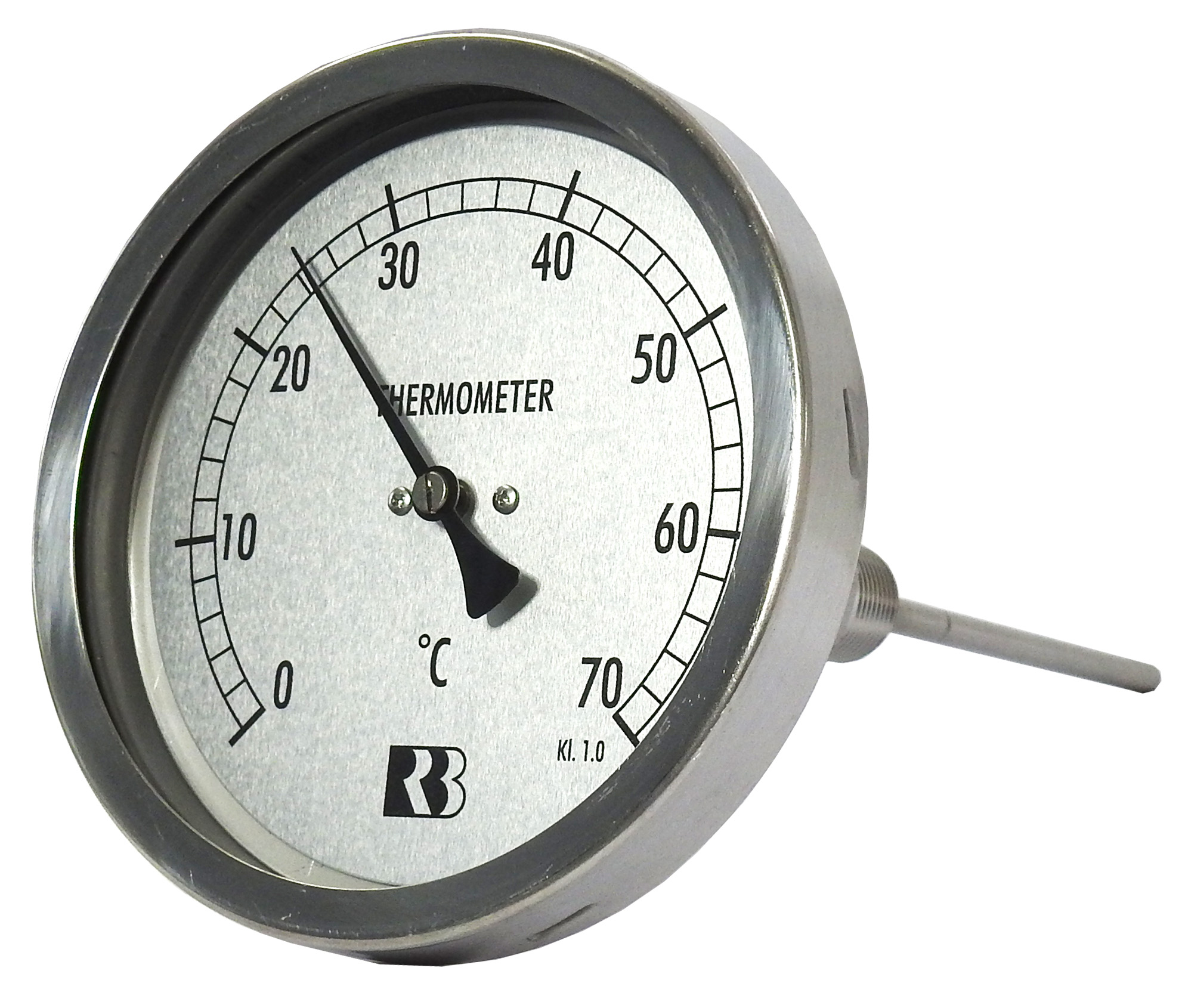
It may sound obvious, but a thermometer is simply a tool that provides temperature information of the food you are preparing. YOU have to make the decisions about when to increase or decrease the heat and whether the food is adequately cooked based on this information. Generally, when the thickest part of the food reaches the required temperature the food can be considered cooked. For example, it is recommended by health professionals that chicken must reach the temperature of 74°C to be fully cooked. Some meat (eg veal) can be cooked to different levels of “doneness”, however there is still a minimum temperature of 52°C that the meat must reach in order to ensure all bacteria has been eliminated.
Please see the Temperature Chart for more information.
When testing if your meat is cooked, the coldest part will be the very centre of the thickest portion. Likewise, when chilling food, the thickest part will be the last to cool. When testing larger food, taking multiple readings from several areas will determine if the entire portion is done.
Keep in mind that different types of thermometers have different sized sensors. A dial thermometer can have a sensor as big as an inch long with your temperature reading being an average of all the materials the sensor is touching. Most digital thermometers have small sensors at their tip, making it important to ensure when penetrating the food that the tip is touching the right area.
Thermometer Capabilities
It is a common misconception that “calibrate” means making some kind of adjustment to a thermometer for accuracy. While sometimes an adjustment is needed, “calibrating” a thermometer simply means testing its accuracy against a verifiable standard. If the thermometer is within the accuracy specification listed by the manufacturer or quality control agency, an adjustment is not required.
The recommended frequency widely varies depending on the type and model of your thermometer. Mechanical thermometers like dial thermometers require regular calibrations as often as daily whereas digital thermometers typically only need to be calibrated yearly. Check the user guide, WHS policy & procedure, or with an appropriate health department for the recommended timeframe.
Thermometers used in a professional capacity typically require a traceable lab calibration certificate. The Ross Brown Sales in-house Temperature Measurement Laboratory can carry out the integral 3-point testing to provide this certification. Our Temperature Measurement Laboratory reference equipment is calibrated by NATA accredited laboratories.
While it is true that the most definitive test of a thermometer’s calibration follows at least a 3-point method, an alternative solution is through the use of a properly made ice bath. This testing method is widely used in the food industries and is recommended by most food agencies when a lab calibration certificate is not necessary. The most common error in an electronic temperature sensor is a shift in the base electrical value which can be seen in an ice bath test. After a digital thermometer has been successfully calibrated at other temperatures, and it can be shown to read accurately in an ice bath thereafter, the likelihood that it reads correctly at other temperatures is greater.
Unless you are testing the thermometer in a properly made ice bath, it is likely the water’s temperature will be higher than the ice point (0°C). When testing in an ice bath, if your thermometer is reading outside of its published accuracy specification, adjust accordingly or contact our service department.
Check the battery compartment. In many thermometers there is a small metal clip that holds the batteries in place. If the batteries are not under this little clip, the thermometer won’t turn on. If the clip is in place and your thermometer still won’t turn on, please contact our service department.
Generally, it will be because your old thermometer is either not as accurate or out of calibration. Test both thermometers in a properly made ice bath to check and adjust accordingly or contact our service department.
Essentially because the temperature of food continually changes while it is cooking, and your ETI digital thermometer is accurate enough to see it. Thermometers will only “lock in” on a given reading if they have a “hold” feature designed to do that.
Digital thermometers are often affected by the emf (electro-magnetic field) generated by the hob. Although rapid cooling may reduce temperature results, it is recommended to record results via heating pans after removing them from the influence of the hob. Alternatively, an infrared thermometer with an adjustable emissivity may be more suitable.
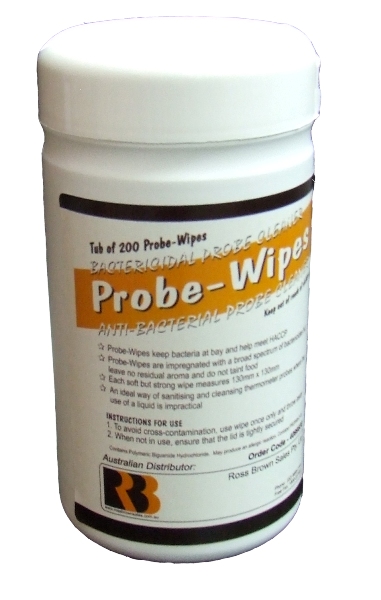
Your thermometer probe should be cleaned every time it comes into contact with raw meat, using cleaning wipes or soap. Your thermometer casing should be cleaned after each use but be careful not to get it wet. Never put the housing of your digital thermometer near water unless it has an IP rating of 66 or higher.
WARNING – IPA and other solvents may cause damage to the case and screen of this instrument
Never leave a thermometer inside an oven, grill, smoker, or microwave while cooking unless it is specifically designed for this. Although some probes are designed to be left inside an oven or grill it is important to not leave your thermometer on the grill hood or close to an open flame. The housing itself (where the electronic components are kept) typically needs to be kept cool and should only be brought near heat for short periods of time so that the unit does not overheat.
It is the rating standards for an instrument’s capability to protect its electronic components from corrosion by water or dust. It is common for electronic thermometers to be splashproof or waterproof and the International Electrotechnical Commission (IEC) rating system classifies the degrees of protection provided. The International Protection Rating code (or IP code) consists of the letters “IP” followed by two numbers.
The first number tells you how protected an instrument’s electronics are from penetration by solids (like dust) and the second number tells you how they stand up against liquids according to the following table:
First Number
| 0 | no protection |
| 1 | Protected against solids objects over 50mm (eg. Accidental touch by hands) |
| 2 | Protected against solids objects over 12mm (eg. Fingers) |
| 3 | Protected against solids objects over 2.5mm (eg. Tools and wires) |
| 4 | Protected against solids objects over 1mm (eg. Tools, wires and small wires) |
| 5 | Protected against dust – limited ingress (no harmful deposit) |
| 6 | Totally protected against dust |
Second Number
| 0 | no protection |
| 1 | Protected against vertically falling drops of water |
| 2 | Protected against direct sprays up to 15° from the vertical |
| 3 | Protected against direct sprays up to 60° from the vertical |
| 4 | Protected against sprays from all directions – limited ingress permitted |
| 5 | Protected against low pressure jets of water from all directions – limited ingress permitted |
| 6 | Protected against strong jets of water eg. For use on shipdecks – limited ingress permitted |
| 7 | Protected against the effects of temporary immersion between 15cm and 1m. Duration of test 30 minutes |
| 8 | Protected against long periods of immersion under pressure |
If, for example, a thermometer had a rating of “IP65”, that would mean that it was tested and found completely protected against dust as well as protected against low pressure jets of liquid from all sides, but NOT protected against immersion, or an accidental drop into the soup!
SuperFast Thermapens
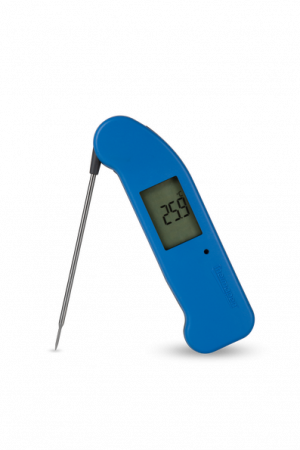
The Thermapen uses Thermocouple Technology as well as a reduced-diameter needle tip on the probe.
Most retailers want to more than double their money, if a product costs $4, they want to charge you $10. The Thermapen is already priced at “Trade Pricing” meaning this is the price we sell it to businesses and general consumers. Big retail chains would have to charge you too much, the retailers that do carry the Thermapen are not making their normal mark-up so thank them if you buy there!
The Thermapen 3 uses two coin cell batteries (CR2032), whilst the Thermapen 4 uses a single AAA battery. Both are commonly found at general stores and retail outlets.
Change the batteries in a Classic Thermapen MK3: How To Video
Change the battery in a Professional Thermapen MK4: How To Video
Yes, both the Classic MK3 and Professional MK4 Thermapen models allow the user to easily switch between the type of degree.
Change the degree on a Classic Thermapen MK3: How To Video
Change the degree on a Professional Thermapen MK4: How To Video
Thermapen batteries are rated for 1,500 hours of use. The auto-off feature will extend the life of the battery and can be enabled/disabled from the battery compartment.
Not literally, however it will tell you (quickly) an accurate temperature reading that you can base your assessment on. Here are some guidelines to cooking times in relation to food safety, however consulting cookbooks, TV shows and recipes for advice on both safe temperature and best cooking temperature for flavour and texture is also valuable. Your individual preferences will also influence your judgement of correct “doneness”.
In use there’s a big difference. Cheaper thermometers are limited by their technology and are mass produced for just a few dollars. On the other hand, the Thermapen is hand-assembled and hand-tested in the UK and uses a professional thermocouple circuit design. This design costs more to make than cheaper, less capable thermometers.
Infrared Thermometers
When measuring the temperature of a grill or grate, the temperature of the surfaces visible through the holes are also factored into the final reading. To accurately measure the temperature of a grate or grill, place a solid surface like an iron plate or skillet on the grill, let it come to temperature then measure the plate or skillet. Spraying a little cooking oil on the plate or skillet will ensure proper emissivity.
“Emissivity” is a measure of a material’s relative ability to emit radiated energy. For more information, please see Emissivity and Infrared.
Infrared thermometers only measure surface temperatures and therefore not very effective at testing if food is properly cooked. We recommend you use a traditional probe thermometer for this.
When measuring liquids such as soups and sauces, ensure you stir vigorously before taking a measurement to balance out the overall internal temperature. Bear in mind steam (even when a liquid is not boiling) can condense on your thermometer and affect the accuracy of your reading.
No, an infrared thermometer will not measure temperature through glass, liquids or other transparent surfaces. Although visible light can pass through it, the infrared thermometer will measure the surface temperature of the window itself, not the object beyond it.
No, an infrared thermometer will not measure temperature through water, it will only measure its surface temperature.
Two variables control the “spot size” of any given measurement:
- The distance to target ratio (DTR) of your particular infrared thermometer
- The distance between your infrared thermometer and the target
For more information, please see spot size.
Yes, an infrared thermometer should be kept free of dirt, dust, moisture, fog, smoke and debris. Particular care should be taken to keep the infrared lens or opening clean and free of debris. For more information, please see Cleaning and Caring for Your Thermometer.
It depends on the type and model of your infrared thermometer. Please refer to your user manual for the full range of features and how to use them.
Highly polished/shiny metals tend to be very reflective and subsequently provide a low emissivity value. With low emissivity materials, energy is reflected not absorbed. For example, a reading from a stainless steel pot filled with boiling water will more likely be closer to 38°C than 100°C because the pot is reflecting the room’s radiation more effectively than emitting its own energy.
Infrared Thermometers can be calibrated for accuracy just like any other thermometer. In Ross Brown Sales’ Laboratory, using industrial black bodies, our technicians calibrate infrared thermometers within Australian Standards and include a 12 month traceable certificate.
If neither an industrial black body nor a comparator cup are available, you can do a quick calibration using a properly made ice bath
Data Loggers
Each logger comes with its own ETI developed software. You can download the software for your logger from our downloads page.
A soft copy of the user manual is included on the software installation CD that comes with your data logger.
ome data loggers come with a built-in cable connector or wireless capability that can connect directly with your computer. Alternatively, some require a separate cradle / data dock that connects with your computer via the USB port.
The most common problem in getting your logger working properly is ensuring you have the correct drivers. This can usually be determined by looking in the System Device Manager on your PC. It is also important to ensure that your logger has the necessary software and is registered before attempting installation.
Yes, each logger will need to be registered with controlling software along with personalised settings selected. Although some loggers come with pre-set defaults and are ready to use right out of the box, it is recommended to customise your particular needs (high and low alarms, frequency of measurements, etc) before use.
One of the key personalised settings for your logger is to allocate a different name to each unit. Most people use either a number, location, or type of material to name their loggers (ie, logger1 / upper_freezer / raw_fish).
